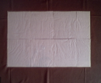
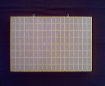
window pane
window pane |
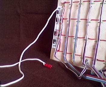
 assembled lattice |
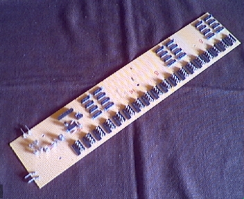
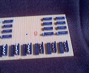
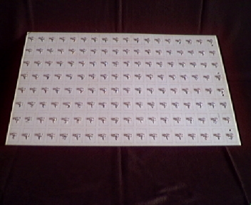 front view of middle board |
 detailed front view of middle board |
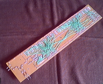
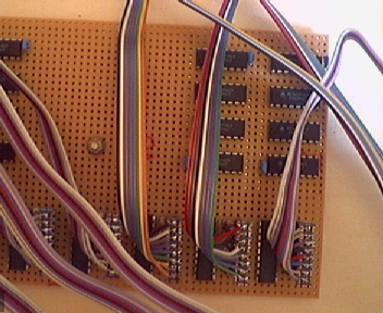
 rear view of middle board |
 detailed rear view of middle board |
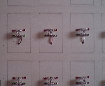
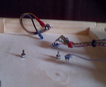
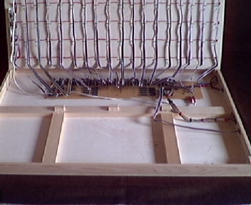
 view of diodes at back |
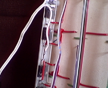 detailed view of diodes at back |
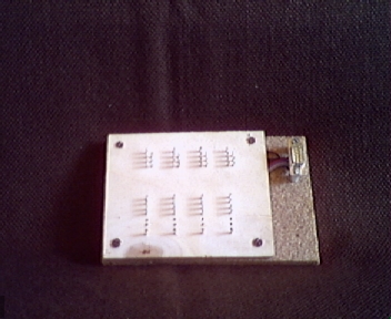
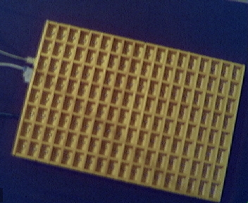
 backplane without circuit |
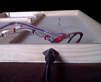
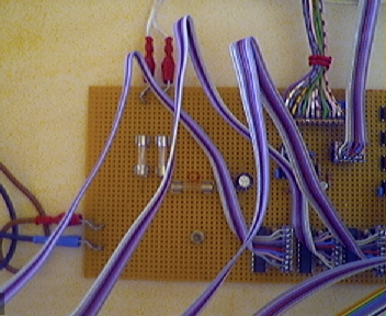
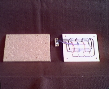
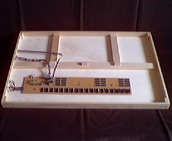 backplane with circuit in place |
 top view of plugs in backplane |
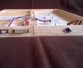 side view of plugs in backplane |
 internal view of plugs in backplane |
 connected plugs |
 connected power plug |
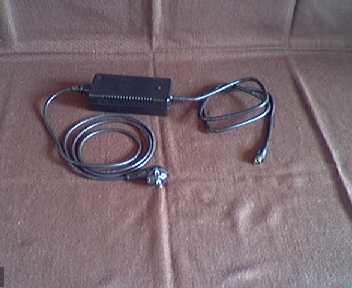 power supply |
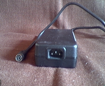 plugs of power supply |
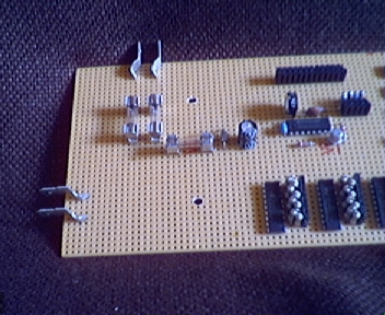 left part of circuit |
 left part of circuit in place |
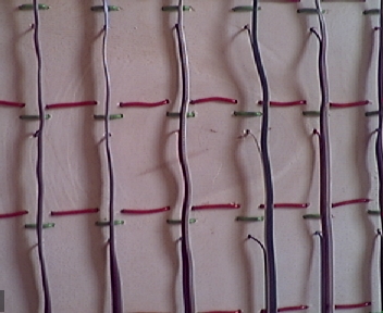
 front view of circuit |
 rear view of circuit |
 right part of circuit |
 right part of circuit in place |
 controller adapter |
 controller adapter (opened) |
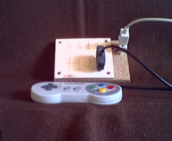 controller adapter with pad attached |
 internal view |
 almost completed, only pane missing (power off) |
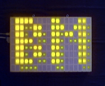
 almost completed, only pane missing (power on) |
 completed (power off) |
 completed (power on) |